Upgrading a Robo3D R1+ Mainboard
by Roderick W. Smith, rodsmith@rodsbooks.com
Originally written: November 30, 2020; latest revision: January 19, 2021
This Web page is provided free of charge and with no annoying outside ads; however, I did take time to prepare it, and Web hosting does cost money. If you find this Web page useful, please consider making a small donation to help keep this site up and running. Thanks!
| Donate $1.00 |
Donate $2.50 |
Donate $5.00 |
Donate $10.00 |
Donate $20.00 |
Donate another value |
|
|
|
|
|
|
|
Introduction
This page documents my experiences upgrading the control board on a Robo3D R1+ 3D printer from its original 8-bit board running Marlin to a new 32-bit board running RepRapFirmware. This now-discontinued printer is a fairly typical Cartesian i3-style printer. If you don't know what any of this means, chances are this page isn't for you. If you do understand it, though, and if you're interested in improving the functionality of your Robo3D R1+ (or of another 3D printer), then read on!
Note that installing a new motherboard in a 3D printer requires familiarity with handling electronics, possibly including crimping new connectors, soldering, and using a multi-meter. You don't need to be a master at any of these things, but you'll likely have to do more than unplug wires from the old board and plug them into the new one. In addition, my project involved installing a bleeding-edge firmware build of a type that's not officially supported by the new board's manufacturer. Finally, I installed a new LCD control panel, again replacing the firmware with an unsupported community-developed branch. You should undertake such a project only if you're comfortable with these tasks, or are willing to learn (and possibly do damage to your printer in the process). Scaling back the project to avoid tasks that give you pause is possible; use your own judgment about how much to undertake.
The index to the left shows the overall structure of this page.
Setting Goals
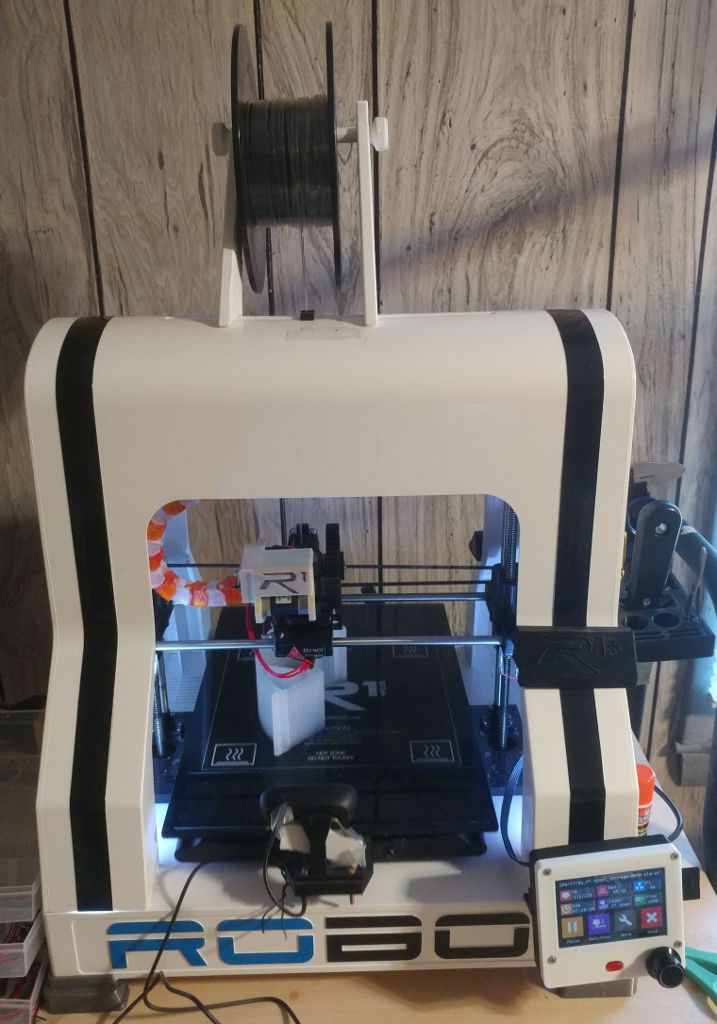
Figure 1: The Robo3D R1+ is a low-cost Cartesian i3-style printer from the mid-2010s
In late 2017, I purchased my first 3D printer: a Robo3D R1+. (Figure 1 shows this printer after my upgrades.) At the time, I found the printer to be frustrating and unreliable; however, I was fascinated by the technology, and I went on to build an entirely different 3D printer (a Kossel XL delta printer design). Three years after buying the Robo3D, I decided to begin upgrading it to make it more reliable and more versatile.
One of the big problems I had with the Robo3D, from the start, was its very primitive and awkward control firmware, Marlin. Although Marlin is popular in the 3D printing world, I disliked it. Changing certain options (such as adding an LCD control screen) requires making changes to source code files, recompiling the firmware, and uploading an entirely new firmware build to the control board. What's more, I had problems with inconsistent bed leveling and with the two Z axis lead screws turning unequal amounts, leading to a tilt in the X-axis gantry that would eventually cause failures when bed leveling via the G29 command. Turning off the hotend heater and then turning it back on again before the hotend cooled down, or changing the temperature before it reached its original set point, would raise a spurious thermal runaway error, which was extremely frustrating. All of these problems should be correctable in firmware, but if there were in-Marlin solutions, I wasn't able to find them.
I much preferred the RepRapFirmware used by the Duet 2 WiFi board I used in my Kossel. In addition to providing a simpler way to configure the printer, RepRapFirmware and the Duet line of control boards provide a Web interface (the Duet Web Control, or DWC) to the printer, enabling uploading files to print via a Web browser (or direct from some slicers), which simplifies the printing process. Similar functionality can be achieved via the OctoPrint software run on a Raspberry Pi. In fact, I used OctoPrint from the start with my Robo3D, but it's not quite as flexible as RepRapFirmware's DWC, in my experience. Using OctoPrint also does nothing to address all the Marlin frustrations I experienced.
The Robo3D's control hardware consists of an Arduino MEGA 2560 and a RAMPS shield. This is a common 8-bit control system, and it's adequate for controlling a Cartesian printer; however, it cannot run RepRapFirmware or other more sophisticated firmware implementations such as Smoothieware, which are designed for 32-bit control boards. Although there are other 8-bit firmware options, replacing the 8-bit hardware with a 32-bit control board seemed like the best way to go. To be sure, a 32-bit CPU is overkill for this printer; but it's worth it to be able to run RepRapFirmware.
A less important problem with the original configuration is that it uses Allegro A4988 stepper driver chips. These chips are popular on low-end 3D printers because they're cheap and reliable; but they are noisy and they're known to create minor surface printing artifacts. Thus, I wanted to replace these chips with something better.
The Robo3D R1+ has five stepper motors: one each for the extruder, X axis, and Y axis; and two for the Z axis. This dual-Z-axis configuration is a good design feature, but as I noted earlier, the two Z axes frequently fell out of alignment, particularly near the top of tall prints. Although it's possible to control two stepper motors via one driver chip, independent control seemed desirable to me, meaning that any board I'd buy would have to support at least five independent drivers. Furthermore, I would like to eventually install two extruders on the printer, with appropriate hot end support, for two-color and/or multi-material printing. This will require another stepper motor and driver, for a total of six. (Alternatively, I could drop back to controlling both Z-axis motors via one stepper using a splitter or, with some boards, a second plug connected to the Z-axis stepper driver on the control board.) Support for at least two hotend heaters may also be desirable, depending on what solution I pick for my eventual multi-extruder configuration.
To be clear, the problems I've just outlined are only the beginning of my difficulties with the Robo3D R1+. Other problems that are not directly addressed by a control board upgrade include the unreliable mechanics of its bed leveling system, difficulty loading filament, excessive ringing/ghosting artifacts, heated bed temperatures that drop off at the edges, a delicate glass bed that's been accumulating chips for years, poor printing tolerances (making it impossible to print certain print-in-place movable objects), and more. This upgrade is only the first of several that I'm likely to perform. I may try replacing some bed components to make it flex less and/or install a BL Touch or similar bed-leveling system to replace the Robo3D R1+'s flaky touch-based system; or I may upgrade the extruder and hotend to something that's easier to load and that provides dual-filament support. Ultimately, I think the Robo3D R1+ can be turned into a decent i3-style printer, even though it was disappointing out of the box.
Selecting Components
With these design goals in mind, I began researching control boards. The need for six stepper drivers in a 32-bit board severely limited my options. Some possibilities (in late 2020) included:
- Duet 2 WiFi — I was happy with the Duet 2 WiFi in my Kossel XL, so this was an option; but it costs $180 and provides only five Trinamic 2660 stepper drivers. A Duex 5 expansion board ($105) adds five more stepper drivers and associated end-stop inputs, heater outputs, etc. Thus, the total price would be quite steep, at $285, although I could start without the expansion board for $180. If I stopped at two extruders, this setup would be overkill; but the extra steppers and inputs would be helpful should I decide to go beyond a dual-extruder setup. Several Chinese clones of this board are also available, for about half the price of the original. Scuttlebutt has it that these clones are generally reliable, but most of them are built with less copper, which means the clones are more likely to overheat in some conditions.
- Duet 2 Maestro — This product is a slimmed-down version of the Duet 2 WiFi. It comes with fewer expansion options — it can't use the Duex 5, for instance, although it does support a more limited dual stepper driver expansion module ($25). It provides Ethernet connectivity, not WiFi, and the latter is preferable, given my printers' location in my house. (Ethernet to WiFi adapters are available, but using one would create an extra hassle and minor expense.) It also comes with a lower price tag of $110. I did not realize that the dual stepper driver module was available at the time I made my purchase. If I had, I might have chosen this board rather than the one I ultimately did.
- Duet 3 — This board provides six Trinamic 5160 steppers and associated I/O ports. It can also work with expansion boards to provide even more features. Thus, it would meet my needs quite well, but at $230, the up-front price is steep. Like the Duet Maestro, this board provides Ethernet connectivity, but not WiFi.
- BigTreeTech (BTT) SKR Pro v1.2 — This board uses an STM32 CPU and supports six socketed stepper drivers, enabling me to choose which steppers to use. It costs about $50, plus about $30 for six Trinamic 2208 stepper drivers. It does not provide a WiFi module natively, but one can be added for $5–30, depending on how this is done. Thus, the total cost is about $85–$110. The big caveat is that the board is designed to run the 32-bit version of Marlin; however, a port of RepRapFirmware for this board, developed by users known as sdavi and Andy Shaw (aka gloomyandy), is available. The result would be almost as capable as the Duet 3, at least on paper, the main drawback being a more limited expansion card capability — a product called the BTT EXP-MOT enables adding up to three more stepper drivers, but this product plugs into the same expansion ports used by the WiFi board. There are ways to get some of this functionality with a WiFi board in place, described later.
- BTT GTR v1.0 — This board is similar to an SKR Pro, but with support for an expansion card (the M5) which can add another five steppers. The GTR alone costs about $65; add steppers and a WiFi module, and the total cost rises to about $100–$125.
- Mellow FLY-CDY — I learned of this board after buying my ultimate choice, so it wasn't in the running for me, but it does look interesting. It uses an LPC1769 CPU, supports up to six socketed stepper drivers, and has a built-in WiFi module. Unusually for a Chinese board that's not an explicit Duet clone, it's advertised as supporting RepRapFirmware, relying on the LPC/STM32 fork of the project. It costs $34 on AliExpress. (I couldn't find an official manufacturer's Web page, although they do have a github repository with documentation.) Adding (presumably six) 2208 drivers brings the price to $50. Given that no extra WiFi module is needed, this makes it an excellent bargain, although I believe it has just 64 KiB of RAM, which would be slightly limiting, as described in the Note earlier.
- Mellow FLY-F407ZG — This is an STM32-based board with a whopping nine stepper driver sockets. Its manufacturer advertises it as compatible with both Marlin and the STM32 version of RepRapFirmware. Although it doesn't include a built-in WiFi port, Mellow makes a separate RepRapFirmware-compatible WiFi module, which is sometimes sold bundled with the board. With the WiFi module, the board costs about $60 on AliExpress; adding nine 2208 driver chips brings the price to about $86. I was unaware of this product when I bought my hardware; but if I were doing my upgrade today, I'd give it serious consideration.
- Mellow FLY RRF-E3 — This board is unsuitable for my upgrade, since it has just four stepper drivers (albeit with plugs for two Z-axis motors); but it deserves mention because it's an inexpensive STM32-based board with a built-in WiFi module. It costs $30 on AliExpress ($45 with four 2208 stepper drivers). Its WiFi module comes with an external antenna, which makes it useful for printers with metal enclosures for their control electronics. It's designed as an upgrade for certain Creality printers, particularly the popular Ender 3; but it can be useful for upgrading other printers, or building a new printer, provided you don't need lots of extra I/O.
- Panucatt Re-ARM — This product costs just $29, with Chinese clones costing a few dollars less. (When I researched it, Panucatt listed the genuine product as being out of stock.) It's a 32-bit board based on the LPC1768 that replaces the Arduino MEGA 2560, keeping the original RAMPS shield, which is where the stepper driver chips and most wires connect. Even adding in five Trinamic stepper drivers and WiFi hardware, the cost would likely come in at under $85. It's designed to run Smoothieware or 32-bit Marlin, but the LPC/STM32 version of RepRapFirmware runs on this board, too. One big drawback of this product is that the RAMPS board in the Robo3D R1+ supports just five stepper drivers. Another is that the Re-ARM board has just 64 KiB of RAM. I only mention the Re-ARM at all because, as a drop-in replacement for the Arduino MEGA board, installation would be simpler, and it would be notably less expensive than most other options.
- Panucatt Kinetica G2C — This board was never seriously in the running for me, but it deserves mention because it might interest you. It's based on an Atmel CPU, and uses its own custom fork of RepRapFirmware; however, as far as I know, this is an old 2.x version, whereas the current development has moved on to 3.x. The board also supports both WiFi and Ethernet (via plug-in modules). It was a non-starter for me because it provides just four built-in Trinamic 2209 stepper drivers, so I wouldn't be able to use either dual extrusion or independent Z-axis control. Like the Mellow FLY RRF-E3, it's intended mainly as an upgrade for Creality 3D printers such as the Ender 3, but it's usable in other contexts, too. For $79–$89, depending on the accessories you buy, it's reasonably priced.
- Other 32-bit boards — Several other 32-bit boards are supported by the LPC/STM32 version of RepRapFirmware; however, most are LPC-based and have the same limitations as the Re-ARM board, most notably a maximum of five stepper drivers. Without the Re-ARM board's advantages, they offered little to interest me; however, they might be of interest to you. To that end, you may want to peruse the boards listed on the LPC/STM32 RepRapFirmware board compatibility page.
In addition to the main control board, I wanted an LCD control panel. To be sure, many users of RepRapFirmware don't bother with such a control panel, instead relying on Web browsers on computers, tablets, or smart phones near their printers. I find it convenient to have a dedicated user interface that doesn't require logging in, though. Broadly speaking, there are three classes of LCD panels that can be used with RepRapFirmware:
- RepRapDiscount displays — Some variants of the RepRapDiscount 12864 display can be used with recent versions of RepRapFirmware, although a Discord comment by Andy Shaw states that the relevant code is currently not compiled for either LPC or STM32 builds. Consult the Duet3D wiki page on displays for information on connecting them to Duet3D control boards and configuring them. These displays require the control board to send them bitmap images, and communicate back by sending information on the turning and pushing of their control knobs, so they require explicit support in the firmware — but the firmware can do with the display whatever it likes. LCDs like this cost about $10 or $20, but they're monochrome-only and users can interact with them only via their control knobs; they are not touch screens. Also, if the code isn't compiled for the STM32 build, they'd be useless on my SKR Pro board. Even if the code were compiled, these boards can't be used at the same time as the RepRapFirmware WiFi module on many third-party control boards. Thus, this class of control board was off my list.
- Generic color TFT displays — Devices such as the BTT TFT series (available in sizes from 2.8 to 7 inches diagonally), the Makerbase (MKS) TFT35, and the Mellow FLY 3.4/7.0 touch screen use 4- or 5-pin serial connections to the motherboard. These control panels send g-code commands to the printer and interpret responses to display temperatures and other information. This design makes the panels at least somewhat compatible with most firmware implementations, although differences in how firmware interprets commands, and in the replies provided, can cause some functions to fail when the printer runs anything but Marlin. (Setting M555 P2 in the RepRapFirmware config.g file might help. This option causes RepRapFirmware's output to look more like Marlin's.) Some of these screens offer explicit RepRapFirmware support in one way or another — third-party developers have created RepRapFirmware-specific firmware variants for the BTT displays, as described later; and ads for the Mellow FLY claim that this display supports RepRapFirmware natively, although I've never used one and so can't say how good this support is. These boards typically cost about $30 or $40 for a ~3.5-inch version, although larger 5- or 7-inch varieties typically cost more than that.
- Duet3D PanelDue — This product can be considered a special case of the preceding type. It comes in 5-inch (about $85) and 7-inch (about $100) variants. A 4.3-inch variant used to be available, but has been dropped from the lineup by Duet3D. (This size is still available from Chinese cloners, though.) My Kossel XL has the previous-generation 7-inch version, and it works quite well. These panels are designed for RepRapFirmware and Duet hardware, although they will work fine with other 32-bit boards running RepRapFirmware. They communicate via a 4-wire serial cable, with an optional larger ribbon cable to enable use of an included SD card socket. They work similarly to generic color TFT displays, although by default they use a PanelDue-specific protocol.
I like the idea of supporting innovators in the 3D printing space, so I was initially drawn to the Duet 2 WiFi and PanelDue; however, the price for this approach was off-putting, particularly when adding the expansion board for my eventual move to a dual-extrusion setup. Also, I already own two of these boards — one for my Kossel XL and another for a SecKit SK-Go2 that I'm about to assemble. I was curious about how RepRapFirmware would work on third-party hardware, and BTT seems to do a better job than most Chinese compnies at honoring open source principles, so I decided to give the BTT SKR Pro v1.2 a try, along with a BTT TFT35-E3.
In addition to these components, some others were required:
- Stepper drivers — My cost figures above specified Trinamic 2208 drivers, since that's what I ultimately bought. These drivers are quieter than the Allegro A4988 drivers that came with the Robo3D R1+, and they support features such as electronic setting of motor current. They do not support sensorless homing, which is the "latest and greatest" feature that's been popularized by the Prusa i3 Mk3; I figured that, because my printer already has functional end-stop switches, I might as well use them. Had I wanted to save some money, I could have re-used some or all of the printer's original stepper drivers. (In fact, replacing only the X and Y steppers would have produced most of the benefits for a third of the price of six new stepper driver chips.) At the moment, on boards with socketed stepper driver chips, RepRapFirmware provides access to firmware control of microsteps and motor current only on the Trinamic 2208 and 2209 chips. Thus, you should stick to these two driver chips if you want to use these features. Check the support page of the wiki to see if this limitation may have changed by the time you read this. Be aware that Trinamic 2208 driver chips are sold on a variety of interface boards that do or do not enable various chip features. I wanted to be able to configure motor current and micro-stepping in software, which meant I needed the UART-enabled version of the product, and in a package that works with BTT's motherboards. I therefore bought drivers of the same brand, paying care to get the UART variant.
- USB B extension cable — Given the geometries involved, this cable is required to provide access to the USB port on the control board. I expect little need to use this USB port, but on those rare occasions when it would be helpful, I didn't want to have to turn the printer on its side and remove the bottom of the case.
- Micro-SD card extension cable — Similarly, this cable is needed to provide easy access to the board's micro-SD card, on which the firmware is stored. As with the USB port, I expect to need access to the micro-SD card very rarely; but when I do, I want that access to be easy.
- ESP8266 WiFi board — A WiFi board is necessary to enable support for RepRapFirmware's "killer feature" of its DWC on the SKR Pro. I know of at least three families of WiFi devices that are suitable for some LPC/STM32 motherboards, but two of these aren't intended for the SKR Pro and so might not work with it, although they may interest you if you're using another motherboard:
- The The Pete's Playground board for the SKR Pro — This small third-party seller (based in Germany) offers a straightforward implementation of the WiFi hardware needed by the SKR Pro, as described in the LPC/STM32 RepRapFirmware wiki. The same seller offers similar products for some other motherboards, too. Another Tindie seller offers the same product made in and shipped from the US, but only for the SKR 1.3 and 1.4; the SKR Pro variant doesn't seem to be available from this seller.
- The BTT RRF WiFi 1.0 — This board is advertised as working with the SKR v1.3 and v1.4; however, the SKR Pro v1.1 and v1.2 have EXP connectors that are reversed in orientation from their lower-priced siblings, which would make using BTT's own product awkward at best, given that the cable lengths must be very short. (Even 10cm cables are said to cause problems.) In practice, I can't promise this board would work at all with an SKR Pro.
- The Mellow FLY WiFi — This product is advertised as being compatible with several LPC-based motherboards, but not with the SKR Pro. It's also sometimes bundled with the Mellow FLY-F407ZG. It includes additional connectors, marked LCD EXP1 and LCD EXP2, that are not present on the other products, so it's conceivable it would work with some expansion products, but the ad is unclear about what these expansion ports support. Another connector is clearly intended for updating the WiFi module's firmware via the DWC, as described later, in Installing Hardware. As with the BTT RRF WiFi 1.0, this board might not work at all with the SKR Pro. Then again, it might — the ad for the Mellow FLY-F407ZG shows a connection to the WiFi module with crossed-over cables, which is what would be required to physically connect this WiFi board to an SKR Pro.
In addition to these pre-built products, it's possible to build such a board yourself for less money; but given the rudimentary state of my soldering skills, buying a pre-built product was definitely the way to go for me, so I bought the Pete's Playground board. The wiring details differ from one 32-bit control board to another, so if you buy another control board, you should be sure to get the right WiFi board. Note that the ESP-01S WiFi module sold by BTT will not run RepRapFirmware's DWC. The WiFi board I bought includes an unpopulated EXP3 connector that provides access to the unused pins from the motherboard's EXP1 and EXP2 connectors into which the WiFi board plugs. Adding pins to this will enable connecting the BTT EXP-MOT expansion card, but only two of the three steppers will be usable. Alternatively, the same Tindie seller offers an adapter card that enables connecting these products together. I haven't used the BTT EXP-MOT or any of the connectors and adapters involved. Given the ultimate orientation of components in my printer, I'd need to move everything quite a bit if I wanted to expand the number of steppers using these products.
- 3M/Command Damage-Free Hanging Clips — I used these to help provide cable management inside the printer's case.
- Electrical connectors — As detailed later, in Installing Hardware, the BTT SKR Pro uses JST XH headers for most of its electrical connections. The Dupont connectors used for most things in the Robo3D R1+ will fit into JST XH headers, with some caveats, detailed later. A couple of Robo3D R1+ wires use Molex KK connectors, which are incompatible and must be swapped for Dupont or JST XH connectors. Single-wire ferrules are also desirable for a few components. I happened to have all of these on hand, as well as a suitable crimping tool. (Needle-nose pliers can do crimping in a pinch.)
- A bigger micro-SD card — The SKR Pro comes with a 128 MB micro-SD card. Although this card is big enough to hold the necessary RepRapFirmware files, it will fill up quickly as files to be printed are added. Also, I've seen suggestions that the quality of the included card is low. Thus, buying a bigger high-quality micro-SD card is desirable. I happened to have a spare 4 GB card, which is working fine.
The total cost for all of these components was about $150.
Printing Parts
Replacing the motherboard of a 3D printer usually requires making some physical changes or adapters because the boards' form factors are not standardized. That was definitely the case for this upgrade. The most difficult part of this process for me was designing a mount for the new board. As detailed shortly, in Installing Hardware, I also needed to literally hack away parts of the inside of the printer's plastic case. To begin, though, I printed the following parts from Thingiverse:
If you use another control board or screen, or if you're upgrading a printer other than the Robo 3D R1+, you may need to find other printable parts to facilitate the upgrade.
Installing Hardware
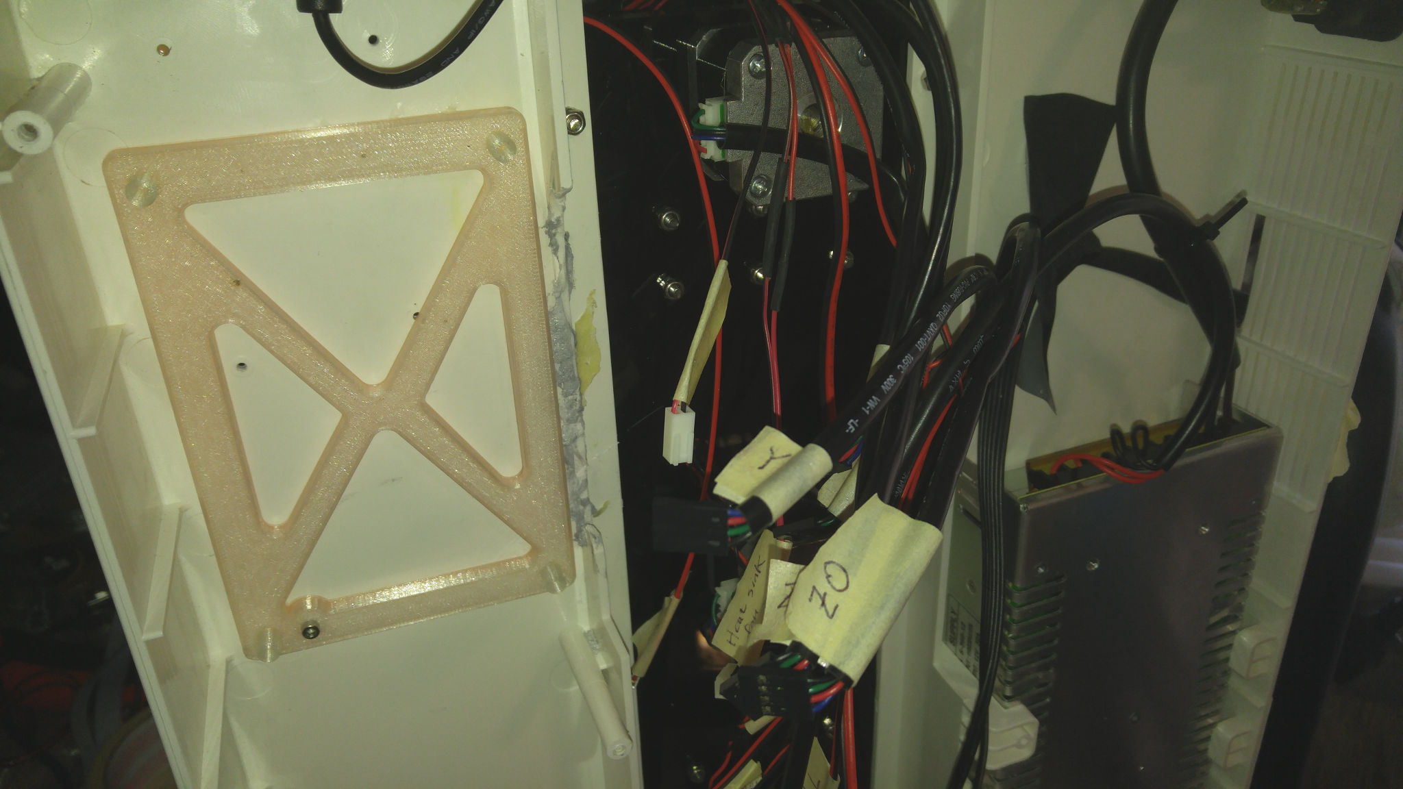
Figure 3: My mounting bracket in the printer
Swapping a control board on a 3D printer is simple in principle, but a bit tedious in practice, because so many wires connect to the control board, and you must keep track of which wires connect to what components during the swap. In addition, the connectors used on the wires may not match the new board, and so may need to be changed. Wire lengths can also be a problem.
Although the BTT SKR Pro fits in the space where the original control board fit, there wasn't sufficient clearance for some of the wires that plug into the board. Thus, I used a Dremel tool to cut away part of the interior dividing wall in the printer, so as to give me sufficient access to the board's connectors.
I used a combination of Elmer's glue and screws to secure the mounting plate in place. Figure 3 shows the bracket installed, with part of the dividing wall cut away. This plate mounts over two small standoffs inside the printer; one is under the bottom-right standoff on the mounting adapter (as oriented in the photo, with the printer on its left side), and you can see the screw securing the other one in Figure 3. The screw used to secure the bottom-right (as oriented in the photo) corner of the new board both secures the board to the adapter plate and helps secure the adapter plate to the printer's case.
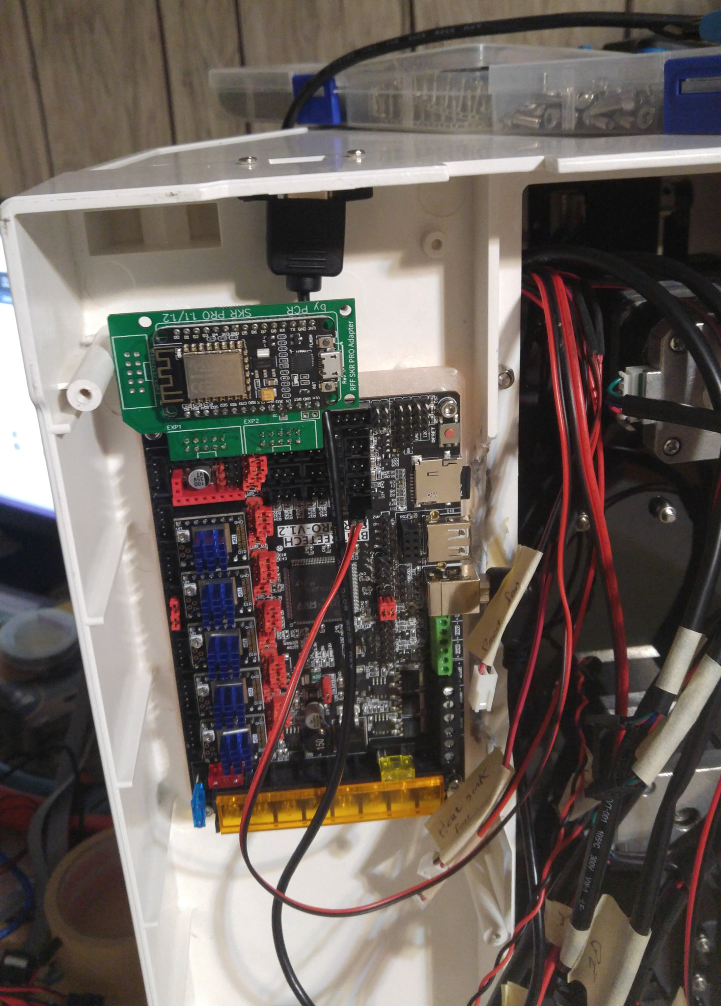
Figure 4: The board mounts on its bracket with its USB port and micro-SD card slot facing the center of the printer
Fan and hotend terminal blocks are on the same edge as the micro-SD and USB ports, making direct outside access to those ports difficult. Thus, I mounted the board with those items facing inward and used extension cables to provide outside-the-printer access to these ports. I drilled two screw holes next to the printer's existing USB port access point and mounted the USB extension cable there. I designed a mounting adapter for the micro-SD card extension that fits in the same slot as the printer's original SD card reader; this design is part of the same Thingiverse project as the SKR Pro mounting plate. Figure 4 shows the new board mounted in the printer, but with almost nothing wired up.
The bulk of the physical installation work involved wiring up the new board. As I removed the original board, I used masking tape to label each wire. One challenge is that the wire connector types didn't match. The original Robo3D wires used a combination of Dupont and Molex KK connectors; but most of the sockets on the SKR Pro board use JST XH connectors. Fortunately, Dupont connectors can fit in JST XH sockets, although they might not be optimally secure, and their orientation is not idiot-proofed. JST XH pin headers are smaller and harder to crimp than their Dupont counterparts. For these reasons, I left the Dupont connectors as-is, paying careful attention to orientation when that's important. Most of the components that used Molex KK connectors were fans or LEDs, and the matching sockets on the SKR Pro were all screw terminals, so I swapped the Molex KK connectors for ferrules to connect to the screw terminals. The two thermistor wires used Molex KK connectors, but their equivalents on the SKR Pro are JST XH connectors, so I needed to cut the wires and crimp on new connectors.
I have some notes on specific connections:
- Power supply — My Robo ran two lines from the power supply to the control board; but the SKR Pro requires three inputs. Fortunately, the Robo's power supply provides three outputs, one of which was unused, so running the third line (using wires supplied by BTT with the SKR Pro) was simple enough. I did need to remove the power supply to gain access to its terminal block, though.
- Stepper motor wires — These required no re-wiring, although the Dupont connectors used by Robo3D make it possible to insert the wires backwards. Orientation is somewhat arbitrary — nothing bad will happen if they're plugged in backwards; but the orientation will affect whether you configure the steppers to drive forwards or backwards. I installed mine with the blue wires facing the power input terminal block.
- Z stepper motors — The Z axis motor connected to the "Z0" stepper on the original Robo3D control board drives the left Z motor, and the "Z1" stepper drives the right Z motor. I connected these to the SKR Pro's "Z" and "E0" connectors, respectively. I then configured RepRapFirmware to drive these motors independently for (Z-axis) bed leveling, as described in the Duet3D wiki and later on this page.
- Endstop switches — The X and Y endstop switches connect to the appropriately-labeled sockets on the control board; but Robo3D's switches are two-wire devices, whereas the SKR Pro provides 3-wire input sockets. These must be connected using the two pins furthest from the stepper driver chips. The original Robo3D design binds the two Z endstop switches (left and right) together, wired in parallel. (These switches operate more like bed probes than traditional endstop switches.) Since these are normally-closed circuits that are activated (opened) when the printer is in operation, the circuit changes state whenever either switch is released during bed probing. I left these wired together in the same way and plugged them into the E0 endstop connector. This configuration was recommended in Duet3D documentation on switch-type bed probes for RepRapFirmware versions 1.x and 2.x; however, if I read it correctly, it should work when connected to the Z endstop switch input with RepRapFirmware 3.x, with trivial configuration changes. I haven't tried this, though.
- Bed thermistor — The heated bed thermistor wire is much thicker than necessary, and used a Molex KK connector. I was unable to crimp the wire into a suitable connector, so I was forced to solder the wires onto a short length of thinner wire, so as to make the connection. A short adapter would have worked, too.
- Thermistor connections — The default mapping in the LPC/STM32 port of RepRapFirmware for this board makes T0 the connector for the hotend's thermistor and T3 the connector for the heated bed. This is clear from the pinout page in the wiki, but might not be obvious by looking at the board.
- Fans and LEDs — The SKR Pro provides only three fan connectors, and they're all screw-terminal types. This is a bit awkward for the Robo3D R1+, which has three fans and two LEDs. Furthermore, the main case fan is attached to its bottom cover, which must be removed to access the control board and other underside components, so that fan must be easily detached from the motherboard. I solved this problem by creating a plug-in adapter for this fan. I then attached the bare-wire end of the adapter and the two LED lighting strips to the fan2 connector. That leaves fan0 for the part cooling fan and fan1 for the hotend fan. An alternative might have been to run some elements, such as the LEDs, directly off of DC output from the power supply. My solution puts the case fan and LEDs under software control, albeit with all three elements tied together. Upon further reflection, I could also have used one of the unused hotend connectors for the LEDs, thus separating them from the case fan.
- TFT35-E3 control panel — This is wired in a simple way. I ran the wires from the control panel mounted in the lower right front corner of the printer through the opening used by other wires inside the printer, with some masking tape to hold down the ribbon cable.
- Short wires — Amazingly, only one wire was too short to reach its new connector. I soldered together a short extension wire. I did have to partially undo the wiring spiral wrap to change where some wires emerged from the main bundle for better wire management and to enable some wires to reach their new destinations, though.
Overall, physically swapping the boards went about as well as I'd expected. Designing the mounting plate was the most time-consuming part of the job, since I needed to print several prototypes before I settled on the final design. If you upgrade your printer in exactly the way I did, or if you can find an existing mount for your printer/board combination on Thingiverse, you won't run into this problem. The second biggest problem was ensuring that the various wires were firmly secured. I had problems with some of them coming loose during testing, but the setup seems to finally be stable.
One issue deserves special mention: Using the ESP8266 WiFi board I purchased, it is not possible to update the WiFi board's firmware without jumping through some extra hoops. Two approaches are possible:
- Computer-to-ESP8266 update — The ESP8266 module includes its own USB micro B connector. This can be connected to a computer and the firmware flashed using the text-mode esptool or GUI NodeMCU PyFlasher tool. This is the same process used to prepare the board in the first place — but as I'd bought my board ready-made, I didn't need to do this initial setup. The LPC/STM32 documentation recommends unplugging the WiFi module from the motherboard before attempting an update in this way; however, on my first firmware update, I did it successfully without unplugging the WiFi module (although I did power off the printer and unplug the motherboard's own USB connection first). Adding another internal USB extension cable to the printer to make it possible to update in this way without opening up the printer might be a reasonable approach, although this would necessitate cutting another hole in the case or otherwise making the extension's end accessible, and it would violate the wiki's recommendation to unplug the WiFi module before updating.
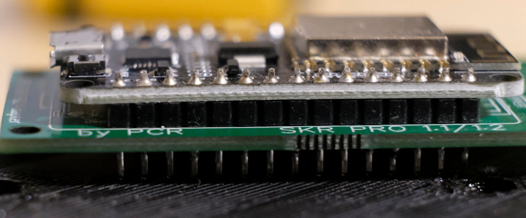
Figure 5: The ESP8266 WiFi board I bought is a combination of two boards
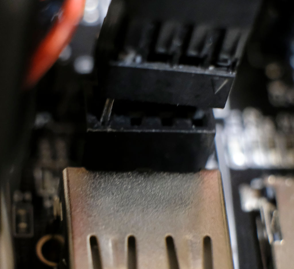
Figure 6: My ESP8266 serial cable, half plugged into the SKR Pro
- DWC-mediated update — On genuine Duet3D boards, updating the WiFi firmware can be done as easily as updating the main firmware, by uploading a file to the System panel in the DWC. To enable this functionality on the BTT SKR Pro (and on most other boards that lack built-in networking hardware), it's necessary to jumper two wires from the Rx and Tx pins on the ESP8266 module to suitable Tx and Rx pins on the motherboard. (The PC.7 and PC.6 pins in the BTT SKR Pro's ESP-01S WiFi port work fine for this; consult the BTT SKR Pro pin diagram to locate these pins.) The 8266wifi.serialRxTxPins line in board.txt must then be updated to specify the pins you've used. Note that the Rx pin on the WiFi module is connected to the Tx pin (PC.6) on the SKR Pro, and the Tx pin on the WiFi module connects to the Rx pin (PC.7) on the SKR Pro. The relevant wiki page notes that a resistor on the ESP8266 adapter board must be changed, but the one I bought already has the correct resistor. Thus, the physical connections involve just two wires. The trouble is that there are no pins on the WiFi adapter board meant to be connected in this way. (Note that the adapter is itself a combination of an ESP8266 module and a separate adapter circuit board, as shown in Figure 5.) As can be seen in Figure 5, the pins on the WiFi module extend far enough through the adapter circuit board that they can be gripped by a 2-pin JST XH connector, but that connection feels very tenuous to me. The other option would be to solder together a connector. (The adapter circuit board includes a couple of unused solder pads that could be used to add proper pins.) Note that the ESP-01S WiFi connector on the SKR Pro is a female socket, unlike most other connectors on the board. Thus, the matching cable end must be male. Judging by the photos on the BTT Web site, it looks like BTT's RRF WiFi v1.0 module for SKR v1.3 and v1.4 boards would be harder to get working with this method of firmware updates. (BTT's product is built as a single circuit board rather than a combination of two, so it's harder to access the WiFi module's Rx and Tx pins.) The Mellow FLY WiFi, by contrast, is designed to be updated only in this way; it appears to have no USB connection.
I performed my first WiFi firmware update using the first method and it worked fine. I then put together a two-wire cable, with a JST XH connector on one end and an eight-pin Dupont shell on the other, with only the two required pins attached. Figure 6 shows the SKR Pro end of this cable, half inserted into the motherboard. I added the following line to my board.txt file to support this configuration:
8266wifi.serialRxTxPins = { PC.7, PC.6 }
Of course, if you use another motherboard, or if you use something other than the serial input on the SKR Pro's ESP-01S socket, you'll need to specify other pins. In any event, with this configuration in place, I was able to downgrade to my previous WiFi module firmware, then re-upgrade to the latest, as a test of this configuration; it worked fine. Time will tell whether the cabling stays put. It could easily be shaken loose from the WiFi adapter module because of vibrations as the printer operates, although at least the JST XH housing is on top of the WiFi module, so gravity is working in my favor.
Configuring RepRapFirmware
Physically replacing a 3D printer motherboard is only half the job; the new board must be told about the hardware it's controlling. Installing RepRapFirmware on the board is quite easy:
- Download the appropriate firmware version for your board and configuration from the LPC/STM32 RepRapFirmware Releases page. Pick the filename with lpc or stm32f4 for your board's CPU type, and with esp8266wifi or sbc, depending on whether you want to use an ESP8266 module or a Raspberry Pi SBC configuration. If you're using a genuine Duet3D board or a clone of one, it should come with RepRapFirmware pre-installed, but you can install an updated version from the Duet3D github page.
- Rename the firmware-{cpu}-{wifi}-{version}.bin file to firmware.bin and place it on a micro-SD card.
- You must also prepare several other files and directories, as described in the LPC/STM32 RepRapFirmware wiki. (This wiki suggests fully configuring the printer at this point. This is possible; but you can also start with a generic configuration file and fully configure the printer later. I describe printer configuration shortly.)
- Insert the micro-SD card into the board and power it on. If you can see the board, you'll see an LED blink as it copies the firmware file to its internal storage
That's basically it for firmware installation. You should be able to connect via a USB port and use Pronterface or a terminal program to connect to the printer and issue an M115 command. The response should reveal that the board is running RepRapFirmware, like this:
FIRMWARE_NAME: RepRapFirmware for STM32F4 based Boards FIRMWARE_VERSION: 3.2-beta3.2_1 ELECTRONICS: STM32F4 FIRMWARE_DATE: 2020-11-13
The next step is to get the printer connected to the local network. LPC/STM32 boards require changes to board.txt so that the firmware knows how to find the ESP8266 module. For the SKR Pro, see this wiki page for details. If you build the ESP8266 module yourself, it will also need to be flashed with the DWC firmware, as described earlier; but mine came pre-flashed, so I didn't need to do that. With these items configured, the rest of this task is covered in the Duet3D wiki. It involves issuing a series of g-code commands to tell the ESP8266 module about your local WiFi network and to connect to it. (You can also enter these commands in your config.g file. Some of the commands need only be issued once, though, and they hold your WiFi password, so you may prefer to do it manually, as I did.) With that done, it should be possible to connect to the printer via a Web browser, and it becomes possible to set up all the printer-specific details, such as the printer's bed size, thermistor type, stepper driver configuration, etc.
Duet3D provides a Web-based configuration tool for RepRapFirmware; however, this tool won't quite do the job for printers running the LPC/STM32 port of RepRapFirmware. Instead, a fork of the configuration tool for these boards is available. Thus, if you're upgrading a printer other than the Robo3D R1+ or using a control board other than the BTT SKR Pro, you should start with whichever of these sites is appropriate for your control board. You may need to make manual changes beyond what the Web configurator can handle. I saw no way to set up a dual-Z-motor configuration using the Web tool, for instance, so I had to edit config.g manually. Once you have a configuration, you might want to compare the resulting config.g configuration file with the one I present shortly; most of that file's settings should apply to other control boards, if you're starting with the base Robo3D R1+ hardware and setting it up in a way that's equivalent to my configuration (in particular, the independent Z axes and my fan/LED configuration).
If your configuration exactly matches mine, or is very close to it, then you may be able to use my configuration files with few or no changes. I'm presenting both a .zip file that bundles all my configuration files together and a few individual files so that you can peruse them online:
- The config.zip file bundle
- The board.txt file, which is a sort of meta-configuration file used by the LPC/STM32 variant of RepRapFirmware but not by Duet3D's main branch
- The main config.g file
- The homez.g file
- The homeall.g file
- The bed.g file
Before you try to use my configuration files on your printer (or use those generated by an online configuration tool), you may want to note a few points:
- Motor direction — The M569 lines in config.g tell RepRapFirmware which way your motors spin. This can vary depending on how you plugged in the motor wires. If your head or bed moves in the opposite direction to the way you expect, either reverse the wire or change S1 to S0 (or vice-versa) in the configuration file. This comment applies to the extruder motor, too. On my printer, despite plugging all the wires in the same way, my extruder takes an S0 parameter (to turn backwards), whereas all the other motors take S1 (to turn forwards).
- Microstepping — I've configured my printer to use 1/128 microstepping in the X and Y dimensions, 1/32 for Z, and 1/64 for the extruder. These are set using the M350 line in config.g. If you used other stepper drivers, you may find that something else is necessary, or simply works better. (I haven't tried to optimize these settings.) The microstepping settings will also affect the steps per mm setting, set via M92.
- Drive mapping — If you connect both your Z-axis motors to a single stepper driver, you'll have to adjust the M584 line in config.g by changing Z2:3 to Z2 and E4 to E3.
- Z leadscrew definitions — The locations of the Z leadscrews are set with the M671 line in config.g. The values in my sample files should be reasonable for the Robo3D R1+; however, this line is not required if you don't want to use the X-axis independent-motor bed leveling feature.
- Thermistors — My printer uses its original Hexagon hotend and the provided thermistor. If you've changed yours, you may need to adjust the thermistor settings, and particularly the M308 lines in config.g. In particular, check the Duet3D wiki's section on thermistor settings.
- Fans — If you wire up your fans and LEDs in a different way than I have, you may need to adjust the M950 and M106 lines in config.g. Note that fan0 should normally be the part cooling fan.
- Control panel support — The M575 line in config.g activates support for the TFT35-E3 LCD control panel. Passing S1 means to use PanelDue-specific coding, S2 uses more generic coding without checksums, and S3 identifies generic coding with checksums. As described later, in Configuring the BTT TFT35-E3, you may need to experiment with these options, perhaps using something non-obvious. You may also need to adjust the baud rate (the B parameter).
- Z homing — The homez.g and homeall.g files both rely on the Z probe to home the Z axis. These files are completely different from what the configuration tool created (although perhaps entering some particular options would generate something similar). Instead, they're based on an example in the Duet3D wiki.
- Independent-Z bed leveling — In RepRapFirmware, the G32 command runs the bed.g macro, which does something related to bed leveling, but precisely what it does varies with the printer type. On a delta printer, for instance, it probes the bed to compute delta-specific parameters. I've configured this macro to probe near the left and right edges of the bed in order to level the X-axis gantry relative to the bed. If run regularly, this should help with the alignment problems I've had with my printer. My bed.g is modified from an example in the Duet3D wiki.
After configuring the firmware, I began testing the printer. I did this in steps — I checked that I could home and control each axis, checked that each axis moves approximately the amount I expected it to, tested the hotend and heated bed temperature controls, tested and calibrated the extruder, and so on. I ran into numerous minor problems. Many of these were caused by loose electrical connections. Others were configuration options that needed tweaking — the Robo3D R1+'s unusual bed probe was particularly tricky to set up.
I performed a PID tuning of both the hotend and heated bed, as described in the Duet3D wiki page on this topic. This process is similar to the same task using Marlin or other types of firmware, so it's probably familiar to you. I saved the results to config-override.g by typing M500 in the DWC's console. I've copied the resulting M307 lines over to config.g. If you're using the Robo3D's original hotend, these values should be close to correct for you, but re-tuning for your own printer is advisable. Be aware that the RepRapFirmware developers implemented a new PID tuning mechanism in version 3.2-beta3.2, to which I upgraded just days after installing my upgrade. My sample files provide the PID tuning values created by the new tuning algorithm.
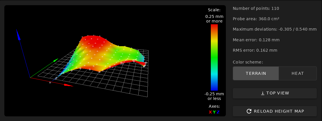
Figure 7: The Robo3D bed probing mechanism produces a poor height map
Near the end of my configuration process, I tried running a G29 mesh bed leveling command. This command is supported by Marlin, and the sample slicer start g-code provided by Robo3D places a G29 command at the start of every print. With RepRapFirmware and the configuration created by the online configuration tool, the process was more thorough (110 probe points vs. 9 with Marlin), and therefore time-consuming. One of RepRapFirmware's great features is that it can display a 3D graphical representation of the bed surface, as shown in Figure 7. As you can see, the result is pretty bad — the deviation across the bed exceeds 0.5mm. I got very different results on some subsequent tries, though. Some of these were better than shown in Figure 7, but others were just as bad. I suspect that the bed level may be affected by removing and replacing the printer's bed. Perhaps this is why Robo3D's sample slicer configurations include a G29 command at the start of each print. As a compromise, I'm manually running a G29 whenever I adjust the bed in any way, but not at the start of each print. (See the upcoming section, Adjusting Slicer Profiles, for information on how I've adjusted my slicer configurations.) Another option, of course, would be to adjust the mesh grid settings (via M557 in config.g) to be less thorough, thus making it reasonable to run a G29 at the start of each print. It's best to run the G29 command with filament removed from the printer and the bed and nozzle thoroughly cleaned. If filament is loaded during a bed probe, the nozzle will leave little specks of filament behind; and if G29 is run again, these specks will throw off the second probe's results. This is awkward if a G29 is run at the start of each print, of course.
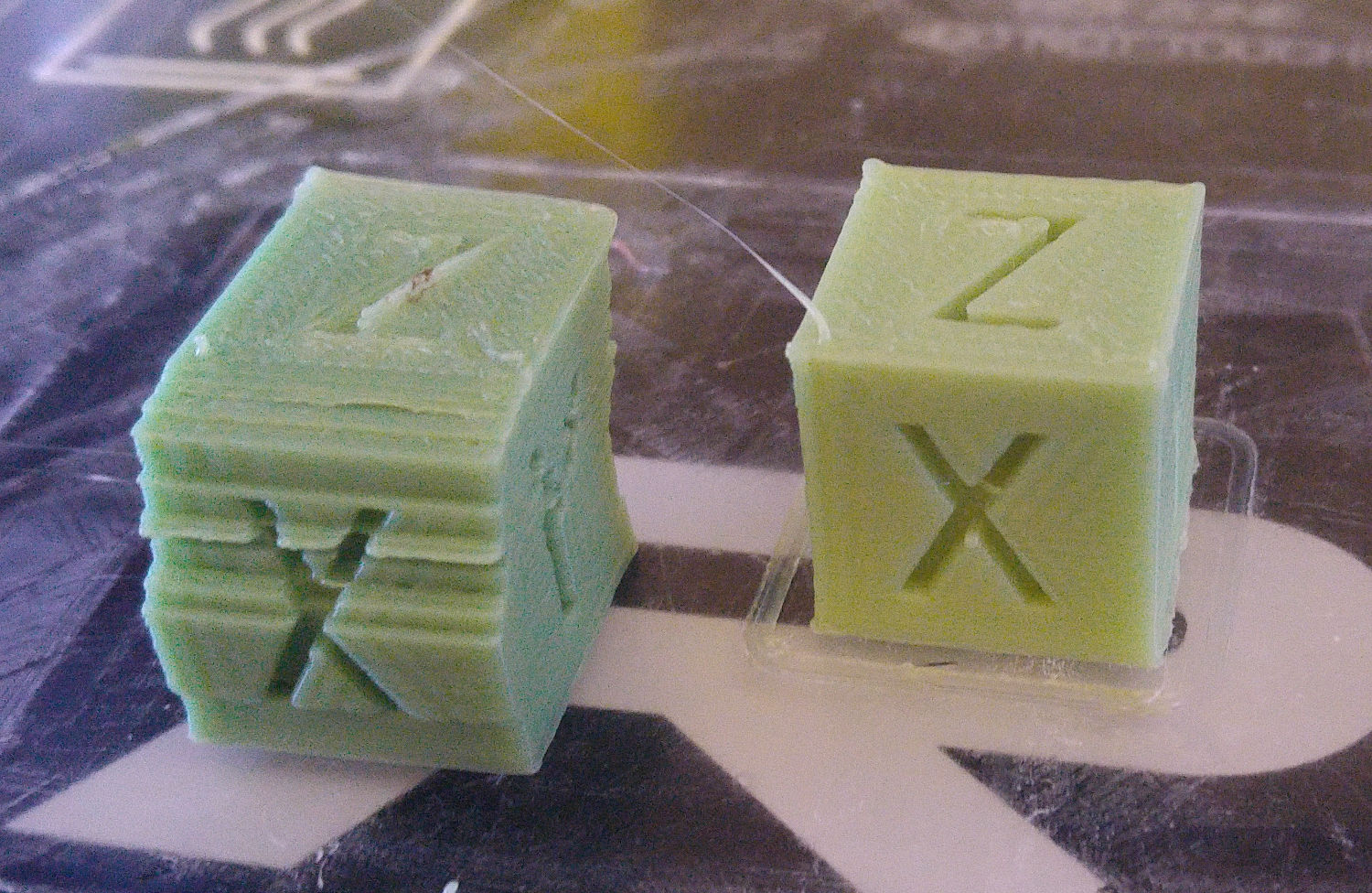
Figure 8: My first test print suffered from layer shifts because of too-high acceleration values
At this point, I began printing, but my first test print was not perfect — it came out with some pretty severe layer shifts on the Y axis. It turns out that I erred in copying the acceleration values (set via M201 in config.g) from my Marlin configuration. This produced far too aggressive acceleration, which resulted in failures. I corrected this problem by reducing the acceleration values. Figure 8 shows my first and second prints (of a simple calibration cube) side-by-side. Once the layer shifting was fixed, I slightly tweaked other settings over the following days to optimize my prints. (My configuration files, referenced earlier, incorporate these changes.)
For some reason, although the steps per mm settings I computed based on my old Marlin configuration for the X, Y, and Z axes were spot-on, this was not true of the equivalent setting for the extruder; I needed to calibrate the E stepper. I found that the optimum value was 3105 steps per mm with 1/64 microstepping. The Marlin configuration for the printer specifies 723.38 steps per mm with 1/16 microstepping, which should work out to 2893.52 steps per mm with 1/64 microstepping — that is, I need over 7% more steps per mm than the stock Robo3D configuration would suggest. On the other hand, a third-party updated firmware specifies 800 steps per mm, which works out to 3200 steps per mm at my 1/64 microstepping, so that's much closer to my figure. Perhaps the discrepancy has to do with different brands or types of filament. (I used Hatchbox PLA for my calibration.)
Configuring the BTT TFT35-E3
The LPC/STM32 wiki has a page on connecting various LCD control panels. I initially found that omitting the serial.aux.rxTxPins line in board.txt was necessary; all of the provided examples resulted in the LCD panel being unable to communicate with the motherboard. I later discovered that the following line in board.txt would also work:
serial.aux.rxTxPins = { A.10, A.9 };
As noted earlier, I used the displays's default 115,200 baud rate, which must be set to the same value on both the printer and the display itself. (I also tested with lower baud rates, including RepRapFirmware's default of 57,600 baud, but the only effect was to slow down some operations.) Activating the control panel requires an M575 line in config.g, the details of which are described shortly.
The BTT TFT-series LCDs' firmware can be updated, and their configuration changed, by copying firmware files (with .bin filename extensions), a font and icon directory (with a name like TFT35, with the number changed to identify the screen size), and config.ini configuration file (for the original BTT firmware only), to an SD card. When that card is inserted in the display and the display is reset or powered on, it will read the relevant files and update itself. (This does not work if the files are placed on a USB flash drive; the update works only via an SD card.) It's possible to update only the firmware file or config.ini file in some cases, although if the new firmware requires icons it can't find, it will insist that you make them available to it.
Literally hundreds of forks of the display's firmware are available; however, I know of two that are worth considering (with two other predecessors of one of these):
- BTT's official version — The display will come with a (likely slightly outdated) version of this firmware. You can download a binary from the Copy to SD Card root directory to update subdirectory. Alternatively, you can download the source code and build it yourself. This version of the firmware works with RepRapFirmware, but isn't optimized for it, so some functions might not work correctly — at least, as of January of 2021. As described shortly, RepRapFirmware support is now being added to this firmware build, but as of January of 2021, those updates are not yet complete. The most notable missing feature prior to mid-January of 2021 is the ability to print from files stored on the motherboard's micro-SD card; attempting to retrieve a list of files results in the display hanging with a "Loading..." message. On the other hand, this version incorporates bug fixes that might not have propagated to the other versions, and supports some features (such as the aforementioned ability to print from an SD card or USB flash drive plugged into the display) that aren't supported by the RepRapFirmware-specific forks. Thus, you might want to use this version if printing from the display's SD card or USB ports is important to you, or if you need some other new or improved feature.
- The Thro42 variant — This version is forked from the JimmymaDdness version, which in turn is forked from the bcmob version. Each of these versions adds new RepRapFirmware-specific features or fixes problems, so the Thro42 version is the best of the three; however, they are based on an older version of the official BTT build, and so are lacking recent updates. The most important improvement is that all three versions add the ability to use the control panel to start prints from files stored on the motherboard's micro-SD card. The Thro42 variant adds the ability to access macros stored on the motherboard's micro-SD card, too. (Other versions of the firmware support macros that are hard-coded in the display's firmware or stored in config.ini; but having the LCD panel run macros supported by the motherboard means you need to maintain just one set of macros for both the DWC and the LCD panel.) All three versions also produce a print summary screen, described shortly, when printing from the motherboard's micro-SD card. These variants drop the ability to start prints from the control panel's own SD card or USB flash drive ports, though. Overall, this is a net gain of functionality compared to the stock firmware, as of December of 2020; however, Thro42 is now working to integrate that functionality back into the stock firmware, so this is changing.
In January of 2021, Thro42 announced that he was working to add RepRapFirmware-specific features to the official BTT build of the firmware, starting with adding the ability to print from the motherboard's micro-SD card. As of late January, that task is incomplete, and in fact the latest version I tested (downloaded on January 18) was badly broken — selecting a file to print from the motherboard's micro-SD card resulted in an error message and a frozen display. (This problem was caused by code added by another developer that broke Thro42's new features.) When I initiated a print from the DWC, it worked fine, although the display did not show the status screen (described shortly). Thus, as of January 18 of 2021, the original Thro42 fork is still my preferred firmware for my TFT35-E3; however, that could change at any time.
Initially, all three of the RepRapFirmware-optimized variants had problems communicating with my SKR Pro motherboard, although the original BTT version did not. The forks seldom connected when the printer was first powered on or reset, but they did connect if, ironically, the "disconnect" option was selected from one of the sub-menus. What's more, these versions of the firmware would often stop communicating with the printer when certain operations were performed manually, such as homing the print head or displaying a list of files to print (or macros, in the case of the Thro42 variant). These problems did not affect the original BTT version of the firmware.
I eventually discovered a fix for these problems: Although the firmware documentation specifies passing an S3 parameter to M575 in config.g, it's actually necessary to pass an S1 parameter, thus:
M575 P1 S1 B115200 ; enable support for PanelDue
According to the Duet3D wiki, S3 identifies "raw mode with checksums," which is how most g-code-based LCDs communicate, whereas S1 specifies "PanelDue mode, checksum required," which seems to imply a PanelDue-specific communications mode. In practice, it seems that the developers of the forks have, whether intentionally or not, made their forks work better with this PanelDue-specific protocol than with the more generic one.
With the S1 version of the M575 command in place, the Thro42 fork began working fine, without any communications glitches. The LCD panel does take a few seconds to connect to the printer, though, when it's first powered on or after a reset. During this time, a flickering "Connecting..." message appears on the screen. When the LCD connects, it beeps and shows the printer's IP address.
If you use the original BTT version, or some other g-code-based display that's not optimized for RepRapFirmware, you should probably pass S2 or S3 instead of S1. (S2 is just like S3, but without checksums. Thro42 has recommended use of this variant with the latest BTT firmware that incorporates his extensions.) Thus, you'd use:
M575 P1 S2 B115200 ; enable support for TFT35-E3
To make the latest versions of the official BTT firmware work with the motherboard's own micro-SD card, you'll also need to set an option in the config.ini file on the display:
onboard_sd_support:1
This setting defaults to a value of 1 ("auto-detect"), which does not (currently) work with RepRapFirmware. As development is proceeding, this detail, and others, are subject to change without notice. If you have problems or questions, I suggest you ask them on the #tft-screen-support LPC/STM32 Discord channel.
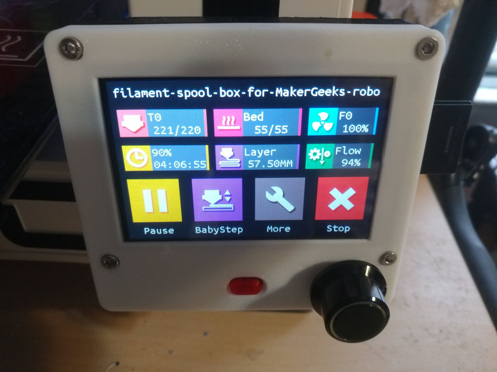
Figure 9: When printing, the TFT35-E3 shows a special print status screen
Depending on the firmware version and how you begin a print, the TFT35-E3 can produce a print status screen, as shown in Figure 9. (Compare this to Figure 2, which shows the main screen when not printing.) This screen appears with the stock BTT firmware when printing from the panel's SD card or USB flash drive; or with the RepRapFirmware-specific forks when a print is launched from the printer's own micro-SD card (whether begun via the DWC or from the LCD panel). This is a useful feature because it removes options that might disrupt the print, such as the option to home the printer; and it adds a BabyStep function to adjust the print height for optimal first-layer adhesion. There's also a crude print status report that shows the elapsed print time and percentage — but no estimated completion time. You can, of course, terminate the print from this status screen. Unfortunately, when starting a print from the DWC with the original BTT firmware, the TFT35-E3 does not show this status display.
All four firmware branches provide a number of options you can set from the display's user interface. In the original BTT build, it's possible to set most of these options using a file called config.ini on the SD card; if you insert an SD card with this filename and reset, the display will read the new options. In fact, this file provides a few settings that don't seem to have equivalents in the user interface. Thus, it's worth perusing this file for options that are worth changing. (For instance, the onboard_sd_support option must be set to 1 before the stock firmware will even show an option to display files on the motherboard to print — but as noted earlier, that option ends up hanging the display.) All three of the third-party builds ignore this file, so you can't adjust options in this way with them.
My experience with the TFT35-E3 so far suggests that it provides useful functionality. With the stock firmware, it can preheat the printer prior to printing, move the print head, and print files from a USB flash drive or SD card. The very latest stock firmware builds add the ability to print from files on the motherboard's micro-SD card, although that function was broken on the specific build I tried. When using the RepRapFirmware-specific forks, and especially the Thro42 variant, integration with RepRapFirmware is tighter, which makes these versions superior. These versions lack some features of the original BTT branch, but at the moment, the features gained outweigh those lost.
Based on my experience with a PanelDue, it's more tightly integrated into RepRapFirmware than is the TFT35-E3 (especially with its stock BTT firmware); for instance, both the PanelDue and the DWC show the same three estimates of print time, based on the file size, layer time, and filament usage. (Recent versions of RepRapFirmware add a fourth time estimate based on the slicer's figures, but that estimate does not appear on the PanelDue.) Overall, as of December of 2020, I'd say that the TFT-35E running BTT's stock firmware provides about 50% of the functionality of the PanelDue, and the Thro42 version provides about 90% of a PanelDue's functionality. The main feature that's missing is display of the completion-time estimates.
Development of the BTT TFT firmware is proceeding at a rapid clip. The first commit to the BTT TFT firmware repository on github is dated July 16, 2019. The bcmob fork appears to have occurred on April 10, 2020. Between then and now (December of 2020), the BTT fork has picked up features such as support for config.ini and updates to the manual g-code entry screen, while the RepRapFirmware forks have added all their RepRapFirmware integration. With Thro42 now working to better integrate RepRapFirmware support into the stock BTT firmware, it's definitely worth keeping an eye on that version of the firmware. If you use that variant, upgrading your display to the latest version is probably worthwhile.
Adjusting Slicer Profiles
Because my printer is now running new firmware, some changes to slicer profiles were necessary. I use several slicers, but PrusaSlicer (the successor to Slic3r Prusa Edition) and ideaMaker are the two I use most often. I therefore focus on the changes I needed to make in these two slicers' configurations.
The necessary changes to slicer profiles focus on the start and end g-code options. Other slicer settings, such as speeds, temperatures, and so on, should not need changes, since they relate to physical characteristics of the printer. (There might be exceptions in some cases, though. For instance, on a delta printer, you might be able to print slightly faster with a 32-bit control board.)
Prior to the upgrade, I used the following as my start g-code in both ideaMaker and PrusaSlicer:
G28 X0 Y0 Z0 ; home all axes
G1 Z5 F5000  ; lift nozzle by 5mm
G29          ; probe the bed
G92 E0       ; zero the extruded length
M420 S1      ; enable use of bed-leveling data
This start code has a few problems with my new board:
- The G29 command will take too long, at least with the thorough 110-point bed probe created by the online configurator. Instead, using G32 to level the gantry and loading the most recent bed map with G29 S1 should do the trick. Furthermore, my bed.g (and hence G32) includes a homing sequence, so the G28 is redundant.
- RepRapFirmware defaults to interpreting extruder moves in a relative way — or at least, that's how the online configurator sets up config.g, via an M83 command. Some slicers assume that the extruder will operate with absolute moves, though. Thus, either an M82 line must be added to the start g-code or the M83 in config.g must be changed to M82. I chose to do the latter.
- RepRapFirmware does not recognize M420; its equivalent is G29 S1, which I've already described.
Implementing these changes, the new start g-code is:
G32         ; home axes and align the bed
G92 E0      ; zero the extruded length
G29 S1      ; use data from most recent height map
The end g-code doesn't strictly require any changes; however, adding a G29 S2 will disable the use of the height map, which can prevent problems with commands used between prints that might require that the height map not be active.
A couple of additional changes are helpful, but not strictly necessary, with ideaMaker. The first of these changes relates to completion-time estimates. As noted earlier, RepRapFirmware's DWC provides up to four such estimates, based on filament usage, file progress, layer time, and the slicer's embedded time estimates. When printing files generated by PrusaSlicer, the DWC presents all four of these estimates. (A fifth estimate can also be produced, as described shortly.) Most of these estimates show as "n/a" when printing g-code generated by ideaMaker, though; only the file progress estimation is shown. RepRapFirmware can generate the layer time estimate if one more line is added to the start g-code:
; layer_height={layer_height}
This line can go before or after the other start g-code lines. Note that it begins with the g-code comment character of a semicolon (;). This is not technically g-code; it's a comment that RepRapFirmware knows enough to parse to extract the print's layer height, which it can then use to calculate a time estimate based on the number of layers printed.
I don't know of a way to coax RepRapFirmware into generating an estimate based on filament usage, which I find is often the most accurate print-time estimate; or to use ideaMaker's own completion-time estimate, which it shows after you've sliced the model. You can, however, use RepRapFirmware's simulation feature to simulate a print: The firmware reads the entire file and calculates how long each move will take. This produces a very accurate fifth completion-time estimate; however, it's an extra (albeit minor) hassle and takes some time, so I rarely do this myself.
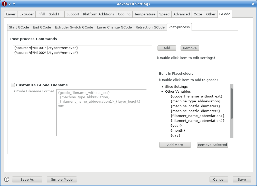
Figure 10: Deleting M1001 g-codes from ideaMaker prevents warnings from appearing
The second optional ideaMaker configuration change relates to the fact that this slicer inserts M1001 and M1002 g-code commands in .stl files that it generates. Neither Marlin nor RepRapFirmware understands these codes, but Marlin quietly ignores them, whereas RepRapFirmware displays a message about an unknown command (and otherwise ignores the unknown g-code). To prevent these warnings from appearing, the Post-Process sub-tab in the slicer's g-code options tab can be used, as shown in Figure 10. To do this:
- Begin to slice an object.
- Edit your slicing template.
- Select the GCode tab, then the Post-Process sub-tab.
- Click Add and, in the resulting dialog box, select Remove All Occurrences of SOURCE as the Command Type.
- Click in the Source field and type M1001.
- Click OK. You should see the removal action appear in the Post-Process Commands area of the Advanced Settings dialog box.
- Repeat the previous three steps, but type M1002 in the Source field.
- When you're done, click Save to save the changes.
Unfortunately, these changes can't be made globally; they must be made to every template, which can be a bit tedious. Fortunately, they're both "bonus features" that aren't really necessary.
Only the changes to the start g-code are really critical, and even then, pre-upgrade g-code intended for Marlin might print with the new motherboard in place. The new start g-code produces better bed leveling, though.
Evaluating the Upgrade
When I first bought my Robo3D R1+, I was disappointed with the printer — but intrigued enough with the technology that I wanted to learn more. After building my own Kossel XL, I'd learned enough to have a good idea of what needed to be done to my Robo3D to get it working the way I wanted, and this control board upgrade was a good first step.
The most obvious change to my operating printer is that it's quieter. The original Allegro A4988 stepper drivers made the printer "sing" whenever it was operating. The new Trinamic 2208 drivers are much quieter — the printer's dominant noises are now its fans and the sounds of the bed and print head moving about. This is a welcome improvement, but it's one that I could have achieved much more easily and inexpensively by replacing the A4988 drivers with Trinamic drivers without swapping out the entire control board.
The ability to properly level the X-axis gantry via a G32 command is a more significant improvement. Although the mesh bed leveling feature (G29 in both Marlin and RepRapFirmware) can theoretically compensate for some lack of alignment, I was constantly frustrated by the printer's deviations, which would, sooner or later, result in its going out of control and driving the head up while trying to perform the G29 command, and the subsequent need to manually spin a lead screw to bring the gantry back into (rough) alignment. This way is much better.
Speaking of bed leveling, RepRapFirmware's ability to display an offset map is informative, and reinforces the need to upgrade to a better Z probing system — perhaps a BL Touch. I may investigate maintenance on the bed first, though; in setting everything up after this upgrade, I noticed considerable play in some of the bed components, which may be exacerbating the probing imprecision. Either way, this will be a project for another day.
The biggest advantage of RepRapFirmware over Marlin, though, is the former's DWC. This enables me to print without using an SD card or OctoPrint. The DWC user interface is smoother and more reliable than OctoPrint, in my experience. I can also make configuration changes in seconds that would take minutes with Marlin.
I can print in any of two or three ways with the printer as it's currently configured:
- From files on the printer's micro-SD card — This is the best way to print on any printer that runs RepRapFirmware, IMHO. It enables easy transfer of g-code files from the computer to the printer, as well as monitoring of the print process via a Web browser. Prints can be started using the DWC or from an LCD control panel. (The stock TFT35-E3 firmware won't do this, although the RepRapFirmware forks will, as of course will a PanelDue.)
- From files on media plugged into the TFT35-E3 — This hardware can send g-code files from an SD card or USB flash drive to the printer one line at a time. This might be a good choice if you can't connect the printer to a local network for some reason — for instance, if you have to take the printer with you to slice files and print them in an unusual location. In most scenarios, though, this method is likely to be less convenient than printing files stored on the motherboard's micro-SD card. This option works only when using the original BTT version of the TFT35-E3's firmware; it's not available on the RepRapFirmware-specific forks.
- From files stored on OctoPrint or an attached computer — This method is how many Robo3D R1+ users, myself included, print with the stock hardware, and it continues to work with the BTT SKR Pro installed. It has some of the same advantages as printing via the DWC, in that files can be uploaded via a Web browser or from some slicers; however, it's a more complex configuration that occasionally fails if the Raspberry Pi or other computer crashes or if the USB connection gets flaky. When using OctoPrint, I find that it's helpful to alter a configuration setting: Go to Serial Connection –> Behaviour and change What To Do On a Firmware Error to the second option ("Cancel any ongoing prints...."). If this change is not made, OctoPrint will tend to disconnect from the printer unnecessarily, because RepRapFirmware is more likely than Marlin to report as errors events such as attempts to move the print head when axes are not homed. Such issues have not affected the few prints I've done this way, but they become annoying when trying to prepare the printer for printing.
In most cases, whatever method is used to print becomes the only (or at least the best) way to fully monitor and control the print. For instance, if you use the DWC to launch a print, neither the TFT-35E nor OctoPrint will show estimations of remaining print time; and if you print files from the TFT-35E's SD card or USB flash drive, neither the DWC nor OctoPrint will provide much in the way of control functionality. Some settings, though, such as the hotend temperature, can be controlled from any interface device. The reset button on the TFT-35E will completely reset the printer, too, no matter what print method is used.
The bcmob, JimmymaDdness, and Thro42 variants of the TFT35-E3 firmware are partial exceptions to this rule of being able to control a print only via the original launch method — they all display a print status screen, shown in Figure 9, when the print is begun from the DWC. It's not quite as informative as what a PanelDue displays, but it's pretty good. This screen includes an elapsed print time and a percentage of the file that's been printed, but not an estimated completion time.
Overall, then, I'm very happy with this upgrade. My Robo3D R1+ has become more reliable, more flexible, easier to use, and is ready for a dual-extruder setup whenever I get around to installing it.
Comparisons to the Duet 2 WiFi
Because I own both a BTT SKR Pro and a Duet 2 WiFi, I can directly compare the two products. Several points stand out:
- Speed of the DWC — In normal operation, the DWC seems just a little bit snappier on the genuine Duet product. One particularly noticeable measure of this is the time it takes to return the DWC to a usable state after hitting the Emergency Stop button: 14 seconds on the Duet 2 WiFi vs. 22 seconds on the SKR Pro. Other features, such as navigating to a new screen in the DWC, don't seem to vary by as much. It's possible that part or all of these differences may be due to factors other than the boards themselves, such as the speed of the micro-SD cards I've used in both of them.
- Software convenience and reliability — As the Duet 2 WiFi was designed in tandem with RepRapFirmware, these two are better integrated than are the SKR Pro with the LPC/STM32 fork of RepRapFirmware. You're more likely to get good official support if you buy a Duet product, and the software is less likely to become abandonware. The LPC/STM32 fork's releases have historically tended to lag behind the main Duet3D RepRapFirmware branch by a few days to a couple of weeks. These are big wins for the Duet.
- WiFi convenience — The Duet 2 WiFi wins this one, because its WiFi chip is built in and requires no special configuration. As detailed earlier, adding WiFi to the SKR Pro requires building a custom WiFi adapter board from an ESP8266 module, buying one ready-made from a third party, or using a dedicated Raspberry Pi. Furthermore, upgrading the WiFi firmware on the Duet 2 is a matter of uploading the binary file to the DWC; but to do this on the SKR Pro requires either extra (poorly documented) configuration and wiring or a manual process involving the WiFi module's own USB port.
- Stepper drivers and connectors — The SKR Pro wins here, with support for six, vs. five, stepper driver chips and one more connector. (Both boards support dual Z stepper connectors on one driver chip.) Furthermore, you can pick which stepper drivers to use with the SKR Pro, whereas with the Duet, you're limited to Trinamic 2660s. (To be sure, these are good stepper drivers.) As the SKR Pro's steppers are plug-in units, they can be replaced if they're damaged or if your needs change.
- 12v or 24v outputs — The Duet 2 WiFi offers outputs for three software-controlled fans, two always-on fans, two extruder heaters, and one bed heater, for a total of eight 12v/24v outputs, six of which are under software control. The SKR Pro provides connections for three software-controlled fans, three extruder heaters, and one bed heater, for a total of seven 12v/24v outputs, all of which are software-controllable. Because it's possible to split a power supply's 12v/24v outputs to create more always-on connections, this gives the SKR Pro the advantage. (That said, I haven't studied the amperage limits of the two boards' various outputs. If you're running too many devices on limited-output circuits, you could run into problems as a result.)
- Limit switches and thermistors — The Duet 2 WiFi provides five limit switch inputs and three thermistor inputs, vs. six and four, respectively, for the SKR Pro. The Duet 2 WiFi also provides a separate 4-pin header for a Z probe. The SKR Pro provides a 5-pin header designed explicitly for a BL Touch, although I've not used that, so I don't know offhand how to configure it in RepRapFirmware. (The official Duet3D wiki provides information on connecting a BL Touch to genuine Duet3D boards, so it can certainly be done with them. Some details may differ on the SKR Pro running RepRapFirmware, though.)
- Display support — Both products support LCD control panels. In both cases, there are separate 4-pin (for the Duet 2 WiFi) or 5-pin (for the SKR Pro) connectors for the PanelDue or generic TFT-style panels and two expansion ports for use with RepRapDiscount-style displays, or to provide access to the display's SD card slot when using a PanelDue with the Duet 2 WiFi. As noted earlier, though, the expansion ports are used to connect the ESP8266 WiFi module on the SKR Pro, which limits your options slightly. If you wanted to connect a third-party TFT to the Duet 2 WiFi, the fifth pin (which passes the output from the reset switch) would either go unconnected or would need to be connected somewhere else. I've not investigated this further; the reset button on the LCD might not reset a Duet 2 WiFi. The PanelDue's reset "button" is a touch-screen feature that does not require a separate wire, so it works with either control board. The transmit (Tx) and receive (Rx) pins are reversed on the Duet 2 WiFi compared to the SKR Pro, so a cable that works for one display won't work for the other, unless you can easily swap those pins.
- Speed of the board — For the most part, as long as the control board can keep up with the printer's physical components, this isn't an issue. Even the original 8-bit board in the Robo3D R1+ is adequate in this regard. I was curious about the speed of the SKR Pro's CPU, though, so I ran a test: I used the RepRapFirmware "simulate print" feature to simulate the printing of a 3D Benchy on my SKR Pro. This process took 35 seconds. I then removed the micro-SD card and plugged it into my Kossel XL with its Duet 2 WiFi. When it booted, the Duet board read the Robo3D's configuration files, so it thought it was the Robo3D. I then ran the same simulation again. This time, it took 71 seconds — the simulation time doubled! Swapping cards the other way (and adding a board.txt file) produced an even more dramatic change: 34 seconds on the SKR Pro vs. 82 seconds on the Duet 3D. Aside from the simulation function, there is little practical effect of this speed difference, so I don't give it much weight, but it is an advantage of the SKR Pro.
- Internal connectors — The Duet 2 WiFi uses Molex KK connectors, whereas the SKR Pro uses JST XH connectors. Both boards use terminal blocks for heater connectors, but the SKR Pro uses terminal blocks for fans, too. The Duet 2 WiFi comes with a collection of Molex KK connectors, so you have everything you need to adjust your printer's wires for the new motherboard, if necessary. Aside from three wires for the power inputs, the SKR Pro comes with no connectors. Having an appropriate crimping tool is helpful when installing either board, unless you're very lucky with your existing wires.
- Power inputs — The Duet 2 WiFi uses a single 12v/24v power input line, whereas the SKR Pro provides (and requires) three separate inputs. I've seen some suggestions that the SKR Pro might support 12v inputs for some components and 24v for others, but I've not investigated this possibility further. The user manual doesn't make any explicit claims on this point.
- Recovery after a power failure — On a Duet 2 WiFi, RepRapFirmware can monitor the input voltage. If it drops precipitously, RepRapFirmware can be configured to save the current print state using the failing dregs of power, thus enabling a resume of the print after power is restored. The current (3.2-beta3.2) build of RepRapFirmware doesn't report the input voltage on my SKR Pro, so I believe this feature will not work with that board, although I've not investigated this in detail.
- Expansion — The Duet 2 WiFi provides a 50-pin expansion connector for use with the Duex products. The SKR Pro supports the more limited BTT EXP-MOT expansion board, which provides three more steppers — but only two more, with the help of adapters, if you use a WiFi module. To get something equivalent to the Duet 2 WiFi's expandability from BTT, you'd need to step up to the GTR board.
- Miscellaneous pins — Both boards provide an assortment of oddball pins and jumpers for various purposes. Most notably, although the SKR Pro provides nothing equivalent to the Duet 2 WiFi's large expansion port, it does offer two smaller sets of "extension" pins, which are not well-documented. If you want to test the board before connecting it to a printer, you'll need to move a jumper on the SKR Pro so as to power it from a USB cable; but the Duet 2 WiFi will just work when plugged into an active USB port.
- USB connectors — The Duet 2 WiFi provides an external USB micro B connector, whereas the SKR Pro provides a USB (non-micro) B connector. In addition, the SKR Pro provides a USB A connector; however, the documentation specifies that only one of the A or B connectors can be active at once, selected via a jumper. I've never tried using the A connector.
- Storage — Both boards use micro-SD cards for storage.
- Physical size and mounting geometry — The Duet 2 WiFi is 134mm x 140mm in size, with external connectors along one of the shorter edges. The SKR Pro is 95mm x 147mm in size, with external ports along one of the long edges. Some terminal block connectors exist on the same edge with the external connectors, making it impractical to mount the board flush with the printer's case for easy access to those external connectors; extension cables are a practical necessity if you want that access. If you want to fit a Duet 2 WiFi in a Robo3D R1+, check this Thingiverse mount. Comparing it to Figure 4, you can see that installing either board requires cutting away part of the under-bed "wall" in the printer. The designer of the Duet 2 WiFi mount doesn't seem to have bothered with extending the micro-SD or USB ports to the outside of the printer, but doing so should be possible, if desired. The Duet 2 WiFi mount is designed with a change in the printer's cooling, too; see the description for details.
Many of these differences are trivial to the point of unimportance, although some of these do require some planning, such as obtaining appropriate internal connectors for the SKR Pro. You'll have to judge for yourself whether features such as the number of stepper drivers, availability of support, and speed of the DWC are important to you.
Overall, the two boards both seem to be quite capable. I'm not qualified to judge the quality of components or manufacturing, though. Time will tell how reliable my SKR Pro is; at the moment, I've been using it for about a month. The Duet 2 WiFi in my Kossel XL has proven to be reliable, with the caveat that I damaged the fan outputs because of some accidental mis-wiring early on. (I was able to work around the damage.)
For many applications, either board will work fine. As noted earlier, I chose the SKR Pro for this upgrade because I plan to eventually use that sixth stepper output to drive a dual-extruder configuration — something that would be possible, but significantly more expensive, with Duet hardware. I also just wanted to try out a different product, since I already have two Duet 2 WiFi boards. A Duet would be preferable if you didn't want to deal with third-party WiFi add-ons or forks of the main RepRapFirmware. Certainly I've invested more time into configuring my SKR Pro than I would have a Duet product. That said, the bulk of my extra time has been spent on the TFT35-E3 LCD panel, not on the SKR Pro itself. If I had to do it over again, I'd consider pairing an SKR Pro with a PanelDue 5i; I've invested time that's worth well over the $50 or so extra cost of the PanelDue over the TFT35-E3, with no real benefit.
If you're considering an LPC board, bear in mind that they all (to date and as far as I know) have half the RAM of a Duet WiFi, which creates limitations that I'm not experiencing. (My SKR Pro actually has slightly more RAM than a Duet 2 WiFi — 196 KiB vs. 128 KiB — but my understanding is that the extra is not currently helpful.) The biggest limitation of the LPC version, at least for me, would be the limit of one HTTP session, since I often connect to my printers from two or more computers, tablets, or phones to prepare and monitor my prints.
References and Additional Information
I've scattered references to outside resources throughout this page. Gathered here are the more useful of these references, along with a few others (mostly specific sub-pages of larger pages I've referenced earlier).
- Informational Web pages
- The original Duet3D pages provide information primarily on Duet hardware. Specific pages that I found most helpful include:
- The Duet3D wiki provides documentation on Duet hardware and information on the RepRapFirmware, including the Duet Web Control component. The RepRapFirmware information is mostly applicable to LPC/STM32 boards running RepRapFirmware. Specific pages I found useful include:
- The BigTreeTech Web site provides information on their products.
- The LPC/STM32 RepRapFirmware wiki provides documentation on this fork of the firmware.
- The Duet RepRapFirmware configuration tool serves as a good starting point to create a starting config.g and related files for genuine Duet3d boards and clones.
- The LPC/STM32 RepRapFirmware configuration tool serves as a good starting point to create a starting config.g and related files for LPC- and STM32-based boards running the unofficial port of RepRapFirmware.
- This 3D Addict article provides a summary of 32-bit control boards available in early 2018. Some of the descriptive text is cut-and-pasted from promotional materials, so take the superlatives with a grain of salt. It's also old enough that it doesn't cover the latest 32-bit boards, including the BTT SKR Pro.
- The RepRap wiki entry on RepRapFirmware provides an overview of RepRapFirmware. It may be useful background reading if you're on the fence about adopting this firmware for your 3D printer.
- Calibrating the E stepper is a critical configuration step described on this page, among others.
- Software downloads
- The main official RepRapFirmware github page hosts the firmware. See the Releases page for links to downloadable binaries for Duet3D hardware, clones, and near-clones such as the Panucatt Kinetica G2C.
- Andy Shaw's LPC/STM32 port of RepRapFirmware is based on github. As with the main branch, you can find downloadable binaries for specific versions on the Releases page. Be sure to get the version for the correct board (with lpc or stm32f4 in the filename) and for using a plug-in WiFi module or a tethered Raspberry Pi (esp8266wifi or sbc) for network access.
- Although I've not tried it, sdavi's branch of RepRapFirmware might be of interest. I'm a little foggy on the details, but my understanding is that Andy Shaw based his version on sdavi's work. Andy Shaw's branch is more recent, with the latest release as I write being made in November of 2020, whereas the latest sdavi release is from December of 2019.
- BTT maintains its own github page with downloads for its products, including a sub-page for its TFT displays. Unlike the preceding github pages, the Releases link does not lead to precompiled binaries; instead, you must download the whole repository or dig into the subdirectories until you find what you need. In some cases, binary builds can lag source code commits by quite a while. Thus, if you're comfortable compiling source code, you might want to compile the latest version yourself. (One of the videos referenced shortly provides pointers on doing this.)
- The bcmob, JimmymaDdness, and Thro42 variants of the BTT TFT firmware are well worth trying on a printer running RepRapFirmware. Of these, the Thro42 version has the most features.
- Compiling the TFT firmware will require you to install the PlatformIO IDE, which in turn is build upon Microsoft's Visual Studio. Versions of both for Windows, macOS, and Linux are available. Start by installing Visual Studio; it provides a tool to search for and install extensions, including PlatformIO.
- YouTube videos
- Building a Better CoreXY Printer — This video, on the Design, Prototype, Test channel, describes upgrading a CoreXY printer with Duet3D hardware, a Slice Engineering Mosquito hotend, and a BL Touch Z probe.
- RepRap firmware on SKR mainboard guide — This video by Teaching Tech describes setting up RepRapFirmware on an SKR v1.4. This isn't quite what I did, but it was very helpful nonetheless. It includes an overview of what's required to wire up the WiFi module rather than buy one pre-built, or to use a Raspberry Pi as a sort of WiFi server.
- RepRap firmware on Big Tree Tech SKR — This video by Chris Riley of Chris's Basement is similar to the preceding one, but goes into more detail about RepRapFirmware setup — but provides less information on do-it-yourself WiFi hardware and TFT displays.
- Duet 2 Maestro & Reprap firmware on SK-GO: Guide for a Marlin user — This is another Teaching Tech video, which provides a good introduction to Duet hardware and RepRapFirmware for those who are more familiar with Marlin.
- Marlin vs. Duet — This video by Design, Prototype, Test provides a comparison between Marlin and Duet.
- BTT TFT35 firmware upgrade - What you should know — This video on the Crosslink channel describes how to upgrade the firmware on BTT TFT LCD panels, including how to compile it from source code.
- SN-28B Crimping tutorial for DuPont pins. — This video by TheRainHarvester demonstrates how to crimp Dupont connectors. The same tools and techniques work for most other multi-pin connectors. (There are many similar videos on YouTube!)
- Communications
- The RepRap forums provide a way to discuss 3D printing issues, particularly involving RepRap designs, with others. These forums include a Duet electronics sub-group.
- The Duet 3D forum provides a place to go with questions about the Duet controller boards and related products.
- The Robo3D forum provides a place to go with questions about the Robo3D line of printers.
- The RRF for LPC/STM Discord group is dedicated to discussions of the LPC/STM32 fork of RepRapFirmware. The developers hang out here.
- You can e-mail me with queries.
copyright © 2020-2021 by Roderick W. Smith
This document is licensed under the terms of the GNU Free Documentation License (FDL), version 1.3.
If you have problems with or comments about this Web page, please e-mail me at rodsmith@rodsbooks.com. Thanks.
Return to my main Web page.